Torque Limiter M1
Progressing Cavity Pump Oil Well Controller
Torque Limiter M1
Progressing Cavity Pump Oil Well Controller
Product Summary
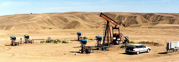
In the picture below, this typical installation site shows the Torque Limiter M1 mounted on the control post facing the well a short distance away from the drive head.

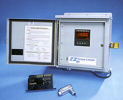
Torque Limiter M1 Product Details
In October of 1994 I was hired by Highland/Corod Inc to design an electronic torque limiting product. Since they were a manufacturer of driveheads, rod string, and downhole PC pumps, they could benefit from an electronic torque limiting product more than most oilfield equipment manufacturers.
Within 4 months the first field prototype was ready to be tested. The company had the use of a well for product testing and the first Torque Limiter M1 was ready. The picture below shows the Torque Limiter M1 for the fist time shutting down a well based on a high torque setpoint.
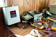
The location of this equipment was in a test shed some 50 m away from the well. As far as anyone knows, this was the first time an electronic device designed specifically for the application was controlling a well using the torque in ft*lbs as the controlling parameter. The concept was patented (US Patent #5,820,350) in early 1996 and covers a number of extensions of the same theme.
Installation - To make the Torque Limiter M1 low cost and to give it flexibility, it was decided to make it an add on to an existing contactor control box. In the following picture an array of 5 wells have their control boxes located on the far right hand side of the picture. This was done for operator convenience and produces a nice clean installation. The pump jack in this picture is not being used and has been replaced by an PC pump system.
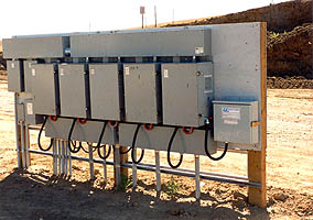
A close up of the control boxes in the picture above is shown below. The Torque Limiter M1 is the small box on the most right hand location on the board. Notice that is connected to the contactor control box using a short conduit. In the contactor control box is located the motor contactor and the Torque Limiter M1's power meter. The RPM sensor line was trenched in by the oil company and is not visible.
Operation & Performance - Coming soon.....
Log Files & Interpretation - The Torque Limiter M1 has 4 different logs stored in memory.
The Program Log was designed to log and time stamp the only major factor that the operator can control that greatly affects the controller's performance. This factor is the torque limit at which point the Torque Limiter M1 will shut the well down. Since this limit is dependent on the equipment used at the well site, it most be programmable to accommodate the wide range of available equipment and their corresponding operating limits. Thus it is possible to program the setpoint with too high a torque limit for the given equipment, leading to equipment failure and possible safety issues. The Program Log acts as sort of an insurance policy that shows how the Torque Limiter was setup and used properly. Being able to log the programming of the torque limit setpoint 32 times essentially can rule out equipment misuse if it is ever in question. Below is an example of the Program Log exactly as it would appear in the log file format.
The Startup Log was designed to log the start up time and date of the drivehead.
The Fast Log in the Torque Limiter M1 contains almost 2000 sample pairs of measured rpm and horsepower. The samples are separated by 4.2 seconds, allowing for considerable detail in a Fast Log. The design criteria for the Fast Log was to have detailed logging at the time just prior to a shutdown. The more information recorded prior to shutdown, the more likely some sort of diagnosis could be made as to the cause of the shutdown.
In this particular example graph of the Fast Log. The profile of the recoil after a shutdown was captured providing unique insight into some of the characteristics of the well. In this case the long recoil time is due to fluid column draining through the pump causing it to work like a motor and turn the surface drive. With decreasing fluid column the drive speed slows down until the system stops. Most interesting is the rather linear portion of the curve during recoil. Given all the factors affecting recoil speed, it is somewhat surprising to see the graph so linear.
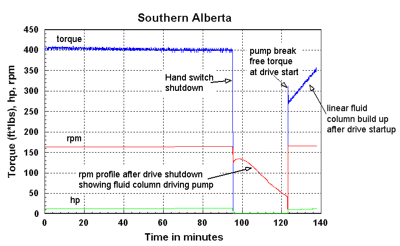
Also of interest of the linearity of the torque curve after startup. This is almost "text book" perfect and shows the increasing heights of the fluid column requiring linearly increasing torque to turn the pump.
The Slow Log in the Torque Limiter M1 contains almost 4000 sample points of torque calculated from measured rpm and horsepower. The samples are separated by approximately 11 minutes, yielding a total logging time of 30 days. The Slow Log was designed to show the changes in torque over a time frame long enough to identify trends, and to establish characteristics of the well.
In this particular example, the Slow Log graph shows the sensitivity of the Torque Limiter M1 and the validity of using torque as a control parameter for oil wells. Of special significance is the tubing rupture shown on the graph. The well was put on test and the tubing ruptured shortly afterwards. Since the pump was now pumping oil only to the rupture point and the oil was not leaving the reservoir. The reservoir depression slowly recovers and thus the pump is ultimately moving the oil over a smaller differential height which results in lower torque requirements.
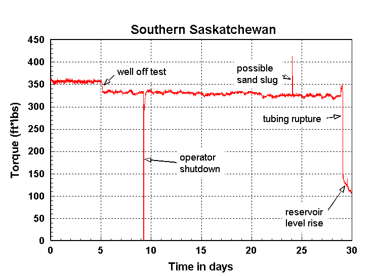
What is interesting is that a number of different observations can be made using only torque as the input parameter. Due to the different time domains for different phenomena it is relatively easy to untangle the different signatures of the various events. Also very interesting is the actual reservoir dynamics behaving in very predictable way. After many observations this has been proven more time true than not.
As time goes by, I expect that the characteristics of the various signatures will become increasingly well defined. Possible to the point where recognizing them can be done in software.
Hardware & Software Design - Hardware design is based around an HC11 single board computer (SBC) made by New Micros Inc. While many companies design complete proprietary boards for their products, my approach was to keep the hardware as generic as possible and place as much functionality in the software as possible. In this particular case design resources were limited, and the production run would likely never make it over a few thousand (at the most) for this model. Thus using an SBC was more practical and allowed the hardware design to be finished in weeks instead of months. I would also say that I used this strategy as it suited me as well. I am specialized in software and not hardware. I can accomplish reasonable digital hardware design, but am weak in complicated analogue design. Also since software is more flexible and upgradeable than hardware, software always wins my favor. This was especially true for the Torque Limiter M1, as the field prototypes played a key roll in providing feedback to improve the product before going into production. Upgrading the software was easy, upgrading the hardware was difficult, and this is generally the case with most embedded products.
The Torque Limiter M1 embedded software was written entirely in Forth. The SBC came with a Forth kernel onboard a customized HC11, which extended with the appropriate Forth routines to complete the project. I wrote all the software for the Torque Limiter M1 including the the realtime scheduler and all the real time processes that provided information to the user routine. I find Forth to be a very powerful language, and is far more suited for embedded control project of a limited size than C because of it's productivity. It is easier to test and debug core software modules and then reuse them extensively. Forth modules can be prototyped and debugged rigorously because of the extremely interactive nature of the language. Some examples of code of a modified sliding window algorithm can be seen below:
1	: GETPOWER ( -- )
2	  POWPTR 1+C!
3	  ADR1 C@ DUP
4	  POWPTR C@ 7 AND POWERARRAY + 2DUP C@ -
5	  PSUM +!  ( add difference between new and old value to sum )
6	  C!
7	  2 <  ( This is a raw NOPOWERLIMIT, done for speed )
8	  IF
9	    0
10	  ELSE
11	    PSUM @ 7F3 >  ( 2035 )
12	    IF
13	      CALRPM @ 0=
14	      IF
15	        RPM @ CALRPM !
16	        2EE
17	      ELSE
18	        STARTUPRPM @ RPM @ - 2EE *
19	        STARTUPRPM @ CALRPM @ - /
20	      THEN
21	    ELSE
22	      0 CALRPM !
23	      PSUM @ 2EE UM* A290
24	      UM/MOD SWAP DROP  ( assumes 8 sample AVG & 75hp power meter )
25	      126 + PSUM @ UM* 3E8
26	      UM/MOD SWAP DROP  ( 1000hp=psum(294+750/204^2*psum)
27	    THEN
28	  THEN
29	  DUP DUP 4E2 > ( clamp hp calculation )
30	  SWAP 0< OR
31	  IF
32	    DROP 4E2
33	  THEN
34	  POWER ! ;
For some applications Forth is extremely powerful.
Conclusion